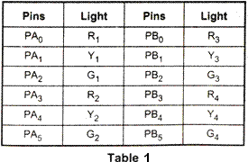


1) Allow traffic from W to E and E to W transition for 20 seconds. 2) Give transition period of 5 seconds (Yellow bulbs ON) 3) Allow traffic from N to 5 and 5 to N for 20 seconds 4) Give transition period of 5 seconds (Yellow bulbs ON) 5) Repeat the process.
The electric bulbs are controlled by relays. The 8255 pins are used to control relay on-off action with the help of relay driver circuits. The driver circuit includes 12 transistors to drive 12 relays. Fig. also shows the interfacing of 8255 to the system
Source program:
MVI A, 80H : Initialize 8255, port A and port B
OUT 83H (CR) : in output mode
START: MVI A, 09H
OUT 80H (PA) : Send data on PA to glow R1 and R2
MVI A, 24H
OUT 81H (PB) : Send data on PB to glow G3 and G4
MVI C, 28H : Load multiplier count (40ıο) for delay
CALL DELAY : Call delay subroutine
MVI A, 12H
OUT (81H) PA : Send data on Port A to glow Y1 and Y2
OUT (81H) PB : Send data on port B to glow Y3 and Y4
MVI C, 0AH : Load multiplier count (10ıο) for delay
CALL: DELAY : Call delay subroutine
MVI A, 24H
OUT (80H) PA : Send data on port A to glow G1 and G2
MVI A, 09H
OUT (81H) PB : Send data on port B to glow R3 and R4
MVI C, 28H : Load multiplier count (40ıο) for delay
CALL DELAY : Call delay subroutine
MVI A, 12H
OUT PA : Send data on port A to glow Y1 and Y2
OUT PB : Send data on port B to glow Y3 and Y4
MVI C, 0AH : Load multiplier count (10ıο) for delay
CALL DELAY : Call delay subroutine
JMP START
Delay Subroutine:
DELAY: LXI D, Count : Load count to give 0.5 sec delay
BACK: DCX D : Decrement counter
MOV A, D
ORA E : Check whether count is 0
JNZ BACK : If not zero, repeat
DCR C : Check if multiplier zero, otherwise repeat
JNZ DELAY
RET : Return to main program


No comments:
Post a Comment